Case study of helicopter air conditioning system and MBSE integration
Introduction
The aeronautics sector is characterised by extremely strict performance, safety, and reliability requirements, making the development of new systems inherently complex. Onboard mechanical systems, such as helicopter air conditioning systems, shall not only meet rigorous technical specifications but also integrate flawlessly into an overall architecture already constrained by space, weight and energy consumption.
Airbus Protect plays a pivotal role in this context, providing expertise to proceed in this complexity, coordinate efforts, and ensure project success.
This article aims to analyse the mechanisms by which Airbus Protect facilitates and successfully completes the development of complex mechanical systems, illustrating this process with the specific case of the design and integration of a helicopter air conditioning system.
We will then highlight the importance of collaboration with suppliers and discuss the potential contribution of MBSE for the future optimisation of these processes.
Methodology & Use-Case
The development of a helicopter air conditioning system follows a sequential phase methodology, incorporating feedback loops for iteration and optimisation, called the “V-cycle”.
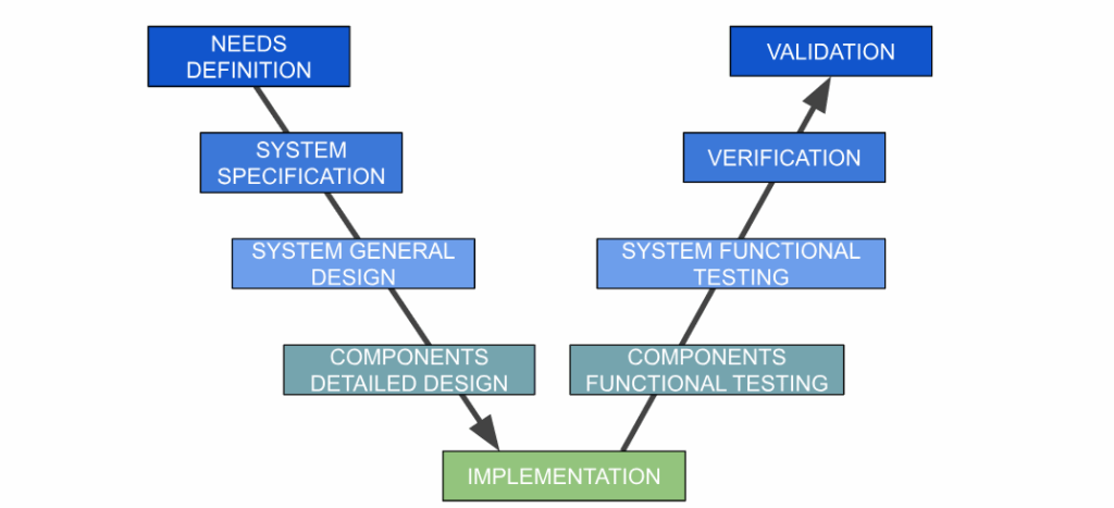
Figure 1: System V-cycle
- Needs Analysis & Specification
The first step involves working closely with the customer to precisely define operational and technical requirements. This includes:
- Thermal performance requirements: Target cockpit / cabin temperature, cool-down time, operation in various environmental conditions (external temperature, humidity, altitude)
- Integration constraints: Available space for equipment, maximum allowable weight, electrical and mechanical interfaces
- Reliability, maintainability, and safety (RMS) requirements: Component lifespan, maintenance intervals, critical system redundancy, aeronautical certification
- Cost and schedule: Budget allocated to development and production, delivery time
These requirements are formalized in a detailed Functional and Technical Specification (FTS) or System / Sub-system Specification (SSS), which serves as a reference document for the entire project.
- Preliminary Design & System Architecture
Based on the specifications, a preliminary architecture of the air conditioning system is defined. This involves:
- Selecting the refrigeration cycle: Vapor compression cycle or air cycle (Brayton cycle), based on performance, size, and weight
- Identifying key sub-systems: Compressor, condenser, evaporator, expansion valve, fans, air ducts, and control system
- Defining interfaces: Physical, electrical, and software interfaces with the helicopter
- Risk assessment: Identifying technical, integration, and performance risks and developing mitigation plans.
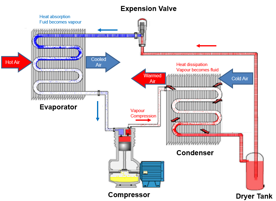
Figure 2: Example of vapor cycle system
- Selection & Collaboration with Equipment Suppliers
Once the architecture is defined, the supplier selection process for the main components begins. This critical process involves:
- Request for Proposal (RFP): Drafting detailed technical specifications for each piece of equipment (e.g., a qualified aeronautical compressor, a compact and lightweight heat exchanger).
- Technical and commercial evaluation: Analysis of supplier proposals based on performance, technological maturity, production capacity, cost, and lead time criteria.
- Co-engineering: Intensive collaboration with selected suppliers. For example, the compressor manufacturer is involved from the design phase to optimize mechanical and electrical integration and ensure the compressor meets the helicopter’s specific load cycles. Regular technical meetings, 3D model exchanges, and joint simulations are conducted.
Interface management: Implementation of a rigorous process for managing interfaces between the various pieces of equipment and with the overall system to avoid incompatibilities and delays.
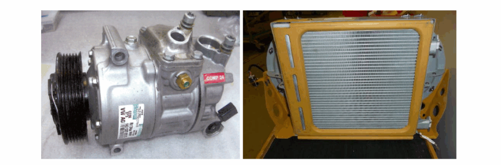
Figure 3: Example of compressor (left) and condenser (right)
- Detailed Design & Prototyping
Detailed design is conducted in parallel with equipment development at suppliers. 3D models and simulations (thermal, fluidic, vibration) are used to optimize the system layout, performance, and robustness. A working prototype is assembled for initial testing.
- Tests & Validation
A series of rigorous tests are conducted:
- Laboratory tests: Verification of individual equipment performance.
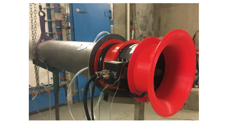
Figure 4: Example of laboratory fan tests
- Bench integration tests: Assembly of the complete system on a test bench simulating the helicopter environment to validate interoperability and overall performance.
- Flight tests: Installation of the system on a test helicopter to assess real-world operation, passenger comfort, and compliance with aviation standards. Adjustments are made based on the test results.
Results & Analysis
The helicopter air conditioning project results in the successful development and integration of a high-performance and compact system that meets aeronautical requirements.
Thermal performance: The system demonstrates its ability to maintain cockpit / cabin temperature within the specified range even under extreme environmental conditions. Cooling time is optimized for rapid comfort on the ground and / or after engine start-up.
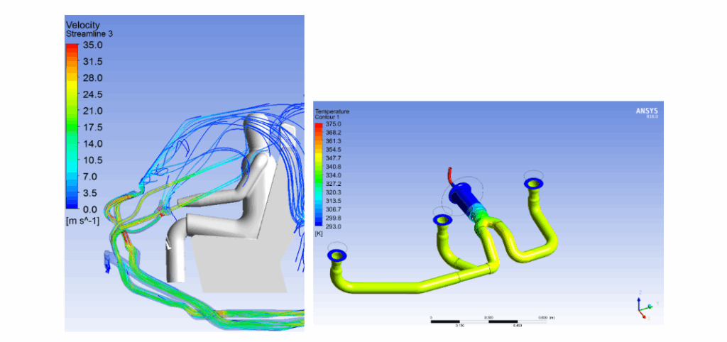
Figure 5: Examples of velocity air flow and thermal simulations for a cockpit air distribution study
- Optimal integration: Through close collaboration with suppliers and advanced 3D modeling, the system is successfully integrated into the helicopter’s constrained space, respecting existing weight limits and interfaces. The total system weight is kept below the initial specification.
- Reliability & Safety: Testing confirms the system’s robustness and compliance with safety standards. Critical components have passed EMC and environmental aeronautical qualification tests (DO-160).
- Supplier complexity management: The co-engineering strategy with suppliers allows for the resolution of technical challenges upstream, thus reducing delays and subsequent modification costs. For example,
- An initial issue related to compressor vibration was identified and resolved by jointly modifying its support and the integration box, avoiding a major impact on the schedule.
- Breakages in the compression subassembly were identified, and design modifications were implemented, thus avoiding poor equipment reliability and future customer dissatisfaction.
- Project deadline: Despite the complexity, the project was delivered on time, demonstrating the effectiveness of the project management methodology and stakeholder coordination.
These results illustrate Airbus Protect’s ability to manage complex system development, mastering the technical aspects, inter-company collaboration, and regulatory constraints specific to aeronautics. The success of the helicopter air conditioning use case validates the methodological approach employed.
Conclusions & Perspectives
The case study of the development of a helicopter air conditioning system highlights the critical importance of Airbus Protect’s ability to structure, coordinate, and execute complex mechanical systems development projects. A holistic approach, from requirements analysis to validation and proactive supplier management, is essential to ensure technical and commercial success. The challenges inherent in integration in constrained environments such as aeronautics require advanced expertise and rigorous interface management.
Perspective: Process improvement with the MBSE method
While the project was a success, the integration of Model-Based Systems Engineering (MBSE) offers significant opportunities to further optimize this type of process in the future. MBSE allows for:
- Formalizing and centralising information: Creating a single model of truth for the system, integrating requirements, architecture, behavior, and testing. This reduces ambiguity and miscommunication between teams and suppliers.
- Improving traceability: Ensuring complete traceability from requirements to testing, including detailed design and supplier contributions. This is crucial for certification and change management.
- Facilitating impact analysis: Enabling rapid assessment of the impact of changes on the entire system, even before their physical implementation. For example, a modification of a supplier component could be simulated to anticipate its effects on overall performance or integration.
- Optimise collaboration: Provide a common language and shared platform for all stakeholders, including suppliers, promoting more efficient co-engineering that is less prone to misinterpretation.
- Reduce costs and time: By identifying issues earlier in the development cycle through simulation and model-based verification, MBSE can reduce the need for physical prototypes and costly test cycles.
- Automatically generate documentation: The model can serve as the basis for generating some of the required technical documentation, accelerating the process and reducing the risk of manual errors.
Implementing MBSE in future complex systems development projects will systematise the approach, strengthen design robustness and accelerate development cycles, thus providing a significant competitive advantage to the company and its customers.


 Safety